


I have plenty of experience with various lighting systems, so now it would be good to finally learn from them and do it right :-). I love Christmas-tree-like decorative lights because they are highly visible from all angles and make people smile. On the other hand, I like to see where I'm going, but a dynamo can't power that all. So I'll make both variants and will switch them as needed. I also like hub generators because they are reliable and never run out of power. But they stop generating when the bike stops moving. A backup accumulator is necessary; if possible, some that would charge from the dynamo and would never need any care. I also don't want to be run into from behind when I grab the brakes - brake light is the solution. And I also want to read the speedo and shifting dials and to charge my phone. Easy, right?

Primary source is a SON Delux hub generator. The lights are calculated to consume its whole output. Secondary source is a battery of four Li-ion cells with total capacity of about 3200 mAh and working voltage between 6 and 8.4 V (which is pretty much the same as the generator gives).
So far, I still stick to discrete 5 mm LEDs. All of them are connected in series of about 6 V threshold voltage (two whites or three reds) to prevent discharging the battery too deeply (under 3 V per cell) if I forget to turn the lights off. There are four sets of lights. First are "low beams": basic headlight and taillight and dashboard illumination. Next two are either "high beams" or omnidirectional decorative yellows, which can be selected alternately by a switch on the handlebars. Last is brake light, powered from main line independent of other lights, so it works even if they are turned off, as long as some of the power sources is online.
Let's split the circuit to several pieces for clarity. This is the whole picture:

S1 switch connects the generator, S2 connects the battery. It is possible to either connect any of the sources independently, or both at the same time - in that case the generator charges the battery. D1 is a bridge rectifier made of 1N4007 diodes. S3 button feeds battery voltage to a tester.
Main power line (the topmost horizontal line in the diagram) supplies both lights and USB voltage converter, so it's possible to shine and charge at the same time (at least until the battery runs out, because the dynamo can't power it all). S6 switch turns on the lights, S7 (ON-OFF-ON) switches between high beams, circus lights and intermediate position where only low beams are on and the battery charges faster.
Brake light is turned on by any of the two S5 normally closed buttons mounted on brake levers. A lever in base position keeps the button pressed and open. When pulled, it releases the button and closes the contact. It doesn't matter how long pull the brake has - long before it engages, the light is already on.

Four 18650 (18 mm diameter and 65.0 mm height) cells salvaged from a dead laptop. I shortened the original 3S2P setup to 2S2P, leaving the connecting metal strips with their tin-plated soldering spots intact - solder is safer than spring contacts.


Three milled plastic cubes (with a lot more material removed since the first picture was taken), two M3 threaded rods and some insulation tape keep it all together. The assembly fits tightly inside the bike's main boom (40×30×2 mm rectangular tube) and I hope it will stay in place and no insulation gets rubbed through.
Li-ion accumulators need careful regulation of charging voltage and current. Current regulation is easily handled by the dynamo: it cannot produce more than 590 mA, which is safely low even for a single cell, and here we have two in parallel. Voltage regulation is trickier. Classic Zener diodes are not precise enough for that, so I used a TL431 integrated circuit. It opens a conductive path between K (cathode) and A (anode) terminals if terminal R (reference) receives voltage of 2.5 V or more. It can't soak all excess dynamo output, but can open some power transistor which can. I copied a circuit designed by Miloš Zajíc (see diagram at the bottom of this page), just with a little different adjusting trimmer.

I have P1 set up so that IO1 and T1 open at 4.1 V. Volt-amper characteristic of the circuit is not perfectly perpendicular, the voltage grows to 4.2 volts at 500 mA (which my cells can take). R1 resistor is there to close T1 when the voltage drops.
The heap of components at the lower right serves no other purpose than indicating the limiter operation, you can omit it altogether. When current flows through T1 transistor, a voltage drop of about 3.2 V appears over D2 diodes and lights up LED1. In this particular application it means the battery is fully charged.
I have two limiters, one for each parallel couple of cells. They double as a balancer: the more charged couple stays on its maximum allowed voltage and current flows through its limiter while the other couple keeps charging. When both indicator LEDs light up, charging is finished.


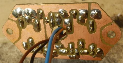
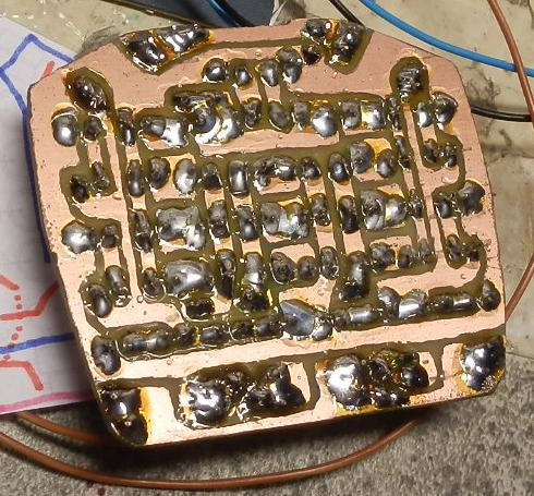
I put both limiters on the same board, together with rectifier bridge and one decorative yellow LED. Be careful with the power transistors: their conductive backplate is grounded, but the grounds are at different potentials on each limiter. Therefore it's necessary to put heat-conductive insulating spacers under them before bolting them to a common heatsink to avoid shorting out the battery.
It's good to know how much juice is left in the accumulators. Electromechanical analogue voltmeter wouldn't survive long, a digital one is beyond my skills and buying a factory product is too boring, so I cobbled together a simple four-LED indicator:

The principle of operation is similar to the voltage limiter: TL431 opens and lights up a LED when P2 feeds it with 2.5 V or more. I have three of these circuits, each of them trimmed for a different voltage (6.2, 7.6 and 8.15 V). As the battery discharges, the lights go out one by one. When fully discharged, just the one at the very left stays on to indicate the tester still works.
Because I only connect the tester to the battery for a short moment, I don't have to care about its power consumption. If you prefer to have the charge level displayed all the time the battery is online, be sure to use much larger resistances for all the resistors and trimmers.


Ignore the three extra blue resistors, they were originally intended to limit base current for BC337 NPN transistors I wanted to use instead of the TL431s. But as it turned out, transistors open so slowly that they are useless for measuring tenths of a volt (base voltage <0.45 V = 0 %, >0.64 V = 100 %). I swapped them for TLs with their legs twisted into proper order.
S3 button which engages the tester is at the left side of main switchbox, the indicator lights are visible through plexiglass headset cover (not while riding, of course).
A bike with a built-in accumulator can double as a powerbank even when parked. The limited amount of energy must be used wisely, therefore the voltage converter must be as efficient as possible. So I used LM2576 switching regulator instead of a simple linear one.

It's not a good idea to connect a battery directly to uncharged capacitor C1, surge current would cause sparks in switch S4 and destroy it quickly. I added inductor L1 to the input to catch the biggest peaks (salvaged from an old radio, colour marking gray-gold-silver-brown-white or maybe reverse order, I don't know nor care what that means) and diode D1 to discharge any induced current.
Principle of operation is the same as last time, the only difference is in component values: L2 coil and C1 capacitor are smaller due to lower input voltage.
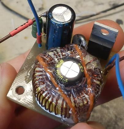


This time I tried to mount the big L2 coil horizontally. It went well and solved many problems, you just need to extend one terminal with a piece of wire to reach the board. The two orange wires are just mechanical anchors. Capacitor C2 fits nicely inside the coil. The integrated regulator is at the edge of the board, bolted to a piece of aluminium to improve cooling (it doesn't heat up much, but it's not negligible). Rest of the components are scattered around the edges and corners.
Last picture shows the whole main switchbox before closing. S3 button for voltage tester is on the left, voltage converter at the front, switches S1, S2, S4 and S6 at the rear. The web of wires needed some pressure to fit in the box (and some more hot glue insulation, of course).
Standard white headlight and red taillight.


Four diodes in the taillight aim directly rearward, two directly sideways and the rest is angled somewhere in between. I mounted resistors R5 on the taillight PCB, having forgotten the trailer supply jack must be between them and the LEDs. OK, never mind, ditch the trailer. R6 and LED3 are in the upper headlight (old Favorit housing with new clear plexiglass window), placed around the edges of the board. Both circuit boards are covered in aluminium tape to improve reflectivity.
More white lights at the front. Optimized for sheer power, blinding of other drivers is prevented by switching to low beams.

LED5 and R8 are in the upper headlight, grouped in the centre of the PCB. They aim slightly down in the same direction as the low beam and illuminate the road.


LED4 and R7 are in the lower headlight. It was originally a Camelion handheld flashlight powered by two D batteries, six diodes connected as 1S6P were fed by voltage booster consisting of a tiny oscillator and inductor. I modified the connection to 2S3P, replaced the oscillator with resistors and shortened the housing. The reflector gives a fairly narrow beam, so I aimed it horizontally forward to pick deer and unlit pedestrians.
Omnidirectional yellow lights scattered around the frame and forks. They serve three functions: to consume excess dynamo power when high beams are off, to improve visibility of the bike in city traffic, and illuminate workspace around the bike's critical components for roadside repairs.

Eight LED5 with R9 are hot-glued to the bottom of the main boom, shining down and sideways. Remaining two LED5 are placed on VL and BVT boards.

LED6 and R10 are glued to inner side of forks, each triple on either side, and illuminate rims, hubs, chain and everything around.
With trigger shifters and the cassette out of sight, the only clue about the selected gear are dials on the shifters, which are useless in the dark. So I cut off some internal ribs and lit them from inside with diodes. Another diode is hot-glued to the tiller, illuminating the speedometer.
I chose red light which doesn't spoil night vision. I wasn't sure how much light will be enough, so I made it adjustable to be sure.

Resistor R12 limits current for LED1 when transistor T2 is fully open. P3 potentiometer sets base voltage for the transistor, R13 limits base current (don't use anything smaller or the transistor mysteriously closes when P3 is turned to maximum).
Theoretically, the transistor circus can be omitted and replaced by a simple potentiometer in series with R12, but it wouldn't be so precise and couldn't be turned off completely.

The same LEDs and resistors as in the taillight. The only difference is these diodes all shine directly rearward, with just a small horizontal dispersion. The housing is riveted from sheet aluminium from an old baking pan, the plexiglass window is grooved for better light distribution, waterproof sealing by Fixall glue. Two screws with V-brake spherical washers hold the box on a rather crooked mudguard holder.
It looks good enough to be worth the work. Low beams are visible even in daylight and they don't blind oncoming drivers more than a headlight of an average car. High beams are strong enough to allow riding pretty fast; the only problem is they are almost exactly in my line of sight on the recumbent's boom, so potholes cast no visible shadows. Power consumption is slightly lower than the average generator output, so the battery slowly charges even with lights on (as long as average speed doesn't drop below 20 km/h). USB charger works as expected, one full charge of a phone and a camera (cca 3 Ah total) didn't drain the battery much, so the step-down converter efficiency is probably OK. Perfect waterproofness of the system was proved in a super strong downpour which was washing it all the way between Klecany and Trója on a cyclepath along Vltava river. The voltage limiter acts funny, indicators sometimes light up after an increase in power consumption (like brake light going on) and then turn off after several seconds. But the battery doesn't complain and the voltage is within limits, so I don't mind.