


A cargo trike is not as narrow and nimble as an ordinary bike, it often doesn't fit on a road shoulder, so it must behave like a smaller and slower car. "Automotive" lighting with indicators, brake lights, fog lights and everything else we can find on motor vehicles should help other drivers understand and treat it that way. The result is the most overcomplicated circuit I have designed so far :-).
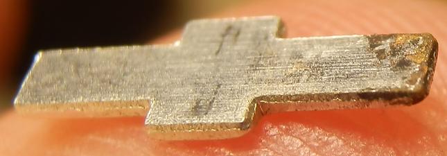
Power is generated by XL-FDD dynohub in rear left 20" wheel and stored in two Li-ion cells connected in series, with a capacity of about 1500 mAh and operating voltage range of 6..8.4 V (pretty much the same what the dynamo uses). Low beams and taillights consume about half of the generator's output, the rest charges the battery (minimum speed for charging is 12 km/h). When high beams are on and I don't ride fast enough (cca 20 km/h), the generated power is not enough and the remaining several dozen mA must be provided by the battery. Long-term energy budget is positive, the battery fully charges after around 8 h of riding with low beams on and every now and then there is enough juice to charge a phone or camera as well.
High beam headlight is made of two high-power LEDs (yes, finally), the rest is my traditional assembly of 5 mm diodes. There are three cold white low beam headlights at the front (bluish cold white is more eye-catching than warm white) and two dimmable red taillights at the rear. Brake light is divided into three parts. There are three indicator lights on each side of the vehicle. And, of course, decorative underglow is a must; this time it's blue. Dashboard is not illuminated: a holder around the speedometer wouldn't be very practical, and the shifting handle is out of sight anyway.
All LEDs are connected in series with threshold voltage around 6 V (white and blue by two, red and orange by three) to prevent draining the battery below the safe 3 V per cell if I forget to turn them off.
Dashed frames and general light bulb symbols mark subcircuits which are described in more detail later. The diagram displays split in half on smaller screens.


Let's start from the left. The generated current is rectified by diode bridge D1, switch S1 disconnects the generator. The rectifier is mounted near the generator this time, so the power going to the switch and mainboard is already rectified - that means the negative wire can double as common ground for all lights on the cargo module, saving one pin in the connector. Excess voltage is cut off by two limiters VL.
Two-pole switch S3 disconnects the battery. Switch S2 toggles charging. If switched on, the generator powers lights and excess current flows into the battery, or from the battery to lights if the generator doesn't make enough. If switched off, the lights are powered either from the generator or from the battery via D1 diode, depending on which of the two provides higher voltage, but no current can flow from generator to battery. The reason for this is Li-ion accumulators can be damaged by charging at temperatures below 0 °C, so I want to be able to turn it off, yet keep the backup battery power for waiting at crossroads. Lesson learned: with charging switched off, a smoothing capacitor should be connected to the generator (drawn in red) or else voltage peaks get lost in the limiters and valleys must be filled by battery.
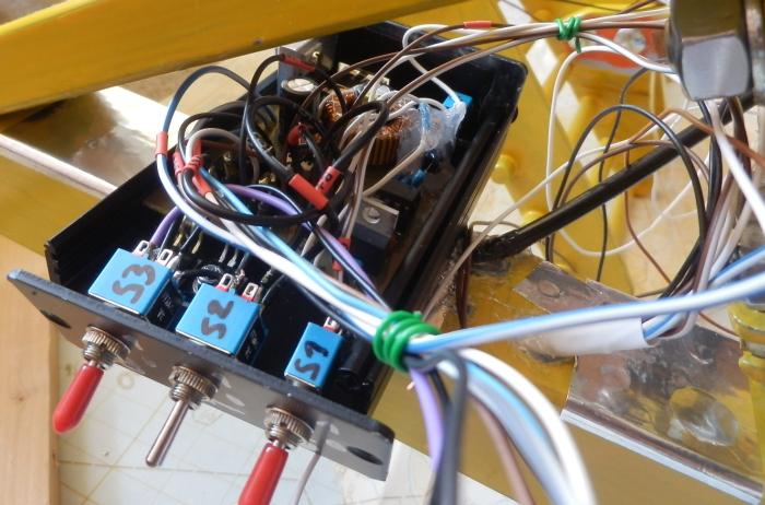

S4 pushbutton connects voltmeter to the battery, S5 switch powers a step-down converter for USB output. Two normally closed buttons S6 are hot-glued to brake levers. When a lever is pulled, the button is released, its contact closes and the current going through it lights up the brake lights (BR). S7 toggles high beams (HB), S8 toggles decorative underglow (DL). So much for the easy stuff...


S11 switch toggles low beams: two small headlights on front corners of the cargo module (LFL and RFL), two rear taillights (TL) and one bigger headlight in the pedal boom (LB). Three-pole switches S9 and S10 control the indicators: one normally open contact to power the blinker circuit (BL), another NO contact to bring the power pulses to the respective indicators (LI or RI), and one normally closed contact to disconnect the bypass around the R3 resistor at the respective small headlight, so it dims down and makes the indicator visible. This workaround makes it possible to merge the headlight and indicator in one common box. It would be possible to use one three-position switch instead of the two, but that wouldn't allow to turn both indicators on at the same time.

Three-position switch S12 controls taillight intensity. In position 3 (right as drawn in the diagram), all current goes directly to the lights, so they shine at maximum level - that's for daytime visibility and for riding in a fog or into the sunset. In position 2 (left), the current filters through parallel resistors R4 and R5 - that's medium intensity for the usual night mode (at least for cases when the driver behind you is not blinded by oncoming cars). In position 1 (off, middle), the current goes through R4 only - that's the lowest setting for nighttime group rides or for parking.
Two 18650 Li-ion cells from a broken laptop, connected in series. Maybe I'll replace them with some bigger Li-pol accupack someday (I'm out of broken laptops for now) to have enough energy for a full charge of my phone (3 Ah). I cut the connecting metal strips so that wires could be soldered to them instead of directly to the cells' end plates (they don't like the high temperatures). Hot glue and insulating tape holds everything together, the resulting lump is wrapped in soft foam (I hope it will not suck in too much humidity) and stuffed into the trike's front boom (40×40 mm square tube). There's also a service connector for winter indoor charging.

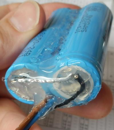
I bought a complete voltage tester this time, a digital one with red display. It consumes about 30 mA of current and it would be wasteful to keep it connected all the time, so it only powers up when a button is pressed. It is placed on the front mudguard, close to the battery. There were originally two huge "faston" automotive connectors on the rear side which I had to cut off so that it would fit into a reasonably small box and the wires could be safely soldered to their contact points (if a connector came loose here, it could short-circuit the battery).


Maximum achievable output current of the generator is 570 mA which these cells can take without trouble. Voltage must be precisely limited to not exceed 4.2 V per cell. I used the same circuit as last time, look there for detailed description. There are two limiters, so don't forget to multiply the component list by two.

Trimmer P1 must be set so that IO1 and T1 start to open somewhere around 4.1 V and are fully open at 4.2 V. LED1 shines when current flows through transistor T1, which means maximum voltage has been reached and the battery is almost full. There are two limiters, one for each cell, which takes care of proper balancing. LED1 indicators are placed on top of front mudguard.
The limiters are placed in the main circuit box, their power transistors use the aluminium casing as heat sink (don't forget to put an insulation layer under them, they are on different potentials). Setting up was pretty dramatic because one of the limiters didn't work at first. I measured everything, removed the reference IC and tested it on a breadboard (it was OK) and just before I began removing the transistor, I found a missing connection between the reference's anode and ground. Whew.


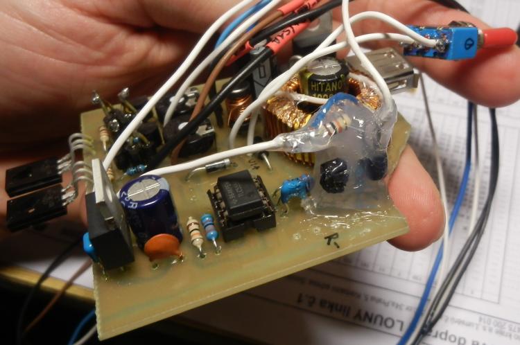
First picture shows the main board with components installed, before final modifications and wiring. Two identical circuits at the top left are the voltage limiters, blinker is at the bottom and USB converter on the right.
Copied from previous installation with no modifications to speak of. The only difference is that pins 2 and 3 in the USB socket are now connected together, which is a standard identification of a dedicated charging port. If they are left unconnected, most smart devices treat the port as weaker and don't draw more than 500 mA from it, even though it can provide more, and some refuse to charge from it altogether. When charging a very hungry phone, my circuit draws 1.3 A at 7 V on its input which means cca 1.8 A on the 5 V output if we disregard all losses, and maybe about 1.5 A if we don't - good, that's roughly the same as what the phone gets from its original 3 A charger.

The only component which warms up during operation is the regulator. It is cooled by an aluminium block bolted to a sidewall of the installation box. The sidewall is insulated from the rest of the box because the regulator's backplate is connected to the DC ground while alternating voltage from the generator may appear on the trike's frame (there are several layers of paint and anodizing between the dynohub and the box, but no actual insulation that could be relied upon). Insulation consists of plastic foil frame glued to the sidewall and insulating washers and heat shrink tubes on the mounting screws (not present yet on the photo).

The socket is covered with a rubber flap to keep rain out.

The board is glued to a sheet aluminium holder which in turn is bolted inside the front boom and doubles as a plug for the battery compartment. Tilt angle of the LEDs (slightly down) was set once for all by bending them with a screwdriver, then a plastic window was hot-glued in front of them. Hiding the lights inside a tube is good for keeping them out of harm's way, not so good for being visible from the sides.


Two high-power LEDs with 15-degree TIR optics (optics bought in Netmart). They only get 2.9 V / 200 mA, the difference in light output compared to their nominal current is insignificant. They are bolted to an aluminium heat sink, overheating is not a problem. The resistor did get pretty hot because it dissipates half a watt, so I installed four 1 W resistors (2S2P) instead of one and it's better now. Maybe someday I'll try to replace it with some switching driver.


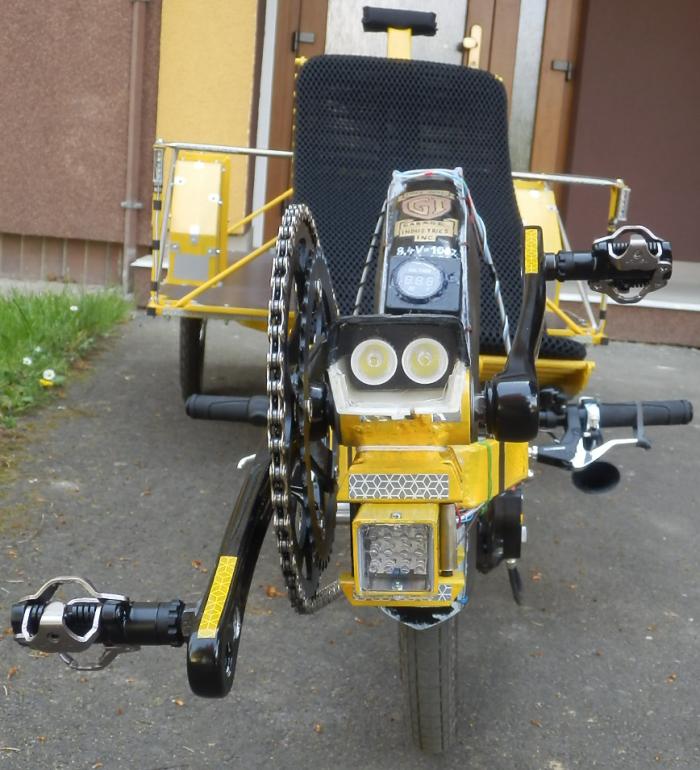
The plastic housing is an old Ruhla headlight, shortened at the front and with new transparent foil in place of the almost opaque original plastic window (at first I planned to use a perfectly transparent thin glass from a broken camera display, but it cracked during the last cut). Light output is excellent, just the colour varies a little: more bluish at the centre and more yellowish at the edges. The headlight now happens to be placed considerably lower than my eyes, so I can see shadows of potholes and sticks on the road.

Two diodes on each side of the cargo module share their boxes with indicators (actually one aluminium box sliced in half and covered with transparent foil). They are intended just to highlight the width of the vehicle, not to illuminate the road ahead, so they are pointed more or less horizontally forward. They illuminate traffic signs at close range pretty well, they can sort of illuminate the speedometer (if I disconnect it and hold it in front of them), and are visible from the driver's seat, so I use them to check if the lights are on during daytime. When an indicator is turned on, the adjacent lateral headlight dims automatically to make it more visible (see above).


5 mm diodes fit neatly in 7 mm lightening holes in the vertical struts at the rear corners of the cargo module. PCBs are glued on their front faces and the LEDs have their leads long enough to stick out at the rear. There was no place for classic resistors, so I used SMD for the first time: tiny, but surprisingly easy to solder. Leads of the diodes are insulated by heat shrink tube, the rest by hot glue and sticky tape. The intensity control resistors R4 and R5 are placed at the switch.


Divided into three groups of three diodes and one resistor: two are built into the lateral struts in the same way as TL, the third is soldered without PCB and hot-glued to the side of the central strut which has no holes in it.
Theoretically, all nine diodes could share one common resistor, but it would be less failure-resistant: if some wire was torn apart, all current would concentrate in the remaining LEDs and probably burn them. Now it's more or less bulletproof. All other lights are designed in a similar fashion.

Two groups of three LEDs share the rear lateral struts with TL and BR, another two share their boxes with LFL/RFL. Last two are placed on the sides of front fork, soldered without PCB and sealed in hot glue. Maybe I'll add some optic fibres to give me visual feedback of the blinking in daylight, so that I don't forget to turn them off (I usually indicate by hands during daytime, but also use the blinkers for double effect).
Generates supply pulses for the indicators.

Stabilizer IO3 with capacitors C3 and C4 provides 5 V supply for the timer. We could also use a cheaper 7805-series stabilizer which is less sensitive for the capacitor parametres, but its voltage drop is higher and might not work properly with 6 V on the input.
IO4 timer (replaceable by NE555, SA555 or similar, the only advantage of TLC555 is lower power consumption) is used in astable mode, the combination of capacitor C5 and resistors R13 and R14 gives blink interval of about 0.7 s. You can find more detailed description in previous article about spinning beacon.
My original plan was that the circuit would end with T2 transistor placed between the indicator lights and ground and the positive supply would go from the respective indicator switches. But I forgot it in my soldering spree and connected the negative terminals of all indicators to main common ground (in addition, there aren't enough pins for separate indicator ground in the nine-pin connector between middle frame and cargo module). So I had no choice but to add a PNP transistor T3, limiting resistor R15 and pull-up resistor R13, reversing the output polarity (now I see I should have moved the R15 between the node under R13 and T3's base, so that it wouldn't make a voltage divider together with R13 and lift the base voltage). They are soldered awkwardly in the air and buried in a lump of hot glue. Speaking of awkward fixes: the blue wire at the bottom of the board substitutes a forgotten connection between the timer's pin 4 and the supply voltage. Without it, the blinker only blinks once.


Four blue LEDs under the front fork are pointed obliquely downward and are directly visible from some angles, so they improve visibility too. The others are hidden under the loadbed, point straight down and are only good for showing off. Total consumption is not negligible (almost 200 mA), so I don't expect to use it for normal everyday riding. All of the LEDs are soldered directly by their leads and insulated with hot glue.

Now you know where the name comes from :-).
Power lines for the generator and battery use 0.5 mm2 copper cables, the rest are thinner 0.34 mm2 from leftover industrial sensor cables. All connections are soldered to ensure reliability, the only two connectors are the one on the generator and the 9-pin canon between midframe and the detachable cargo module (I'd prefer something threaded and waterproof, but I was too impatient to wait for the coronavirus calamity to end and GM Electronics to open again). The following pin numbering is mostly just for my reference:
| Pin | Marking | Colour | Meaning |
|---|---|---|---|
| 1 | R- | thick blue/white+blue | main common ground |
| 2 | ZS+ | black | taillights |
| 3 | BS+ | brown | brake lights |
| 4 | OS+ | brown | underglow |
| 5 | G+ | thick brown/white+brown | generator positive wire |
| 6 | LB+ | white | left indicator |
| 7 | PB+ | white | right indicator |
| 8 | LPS+ | black | left headlight |
| 9 | PPS+ | black | right headlight |
Rectifier bridge is glued next to the generator, current-limiting resistors are placed next to their LEDs, voltmeter is bolted close to the battery. All the remaining electronics are concentrated on one board in a box under the seat, close to all switches on seat and handlebars and relatively out of harm's way (as long as puddles don't get too deep - the box is not watertight).


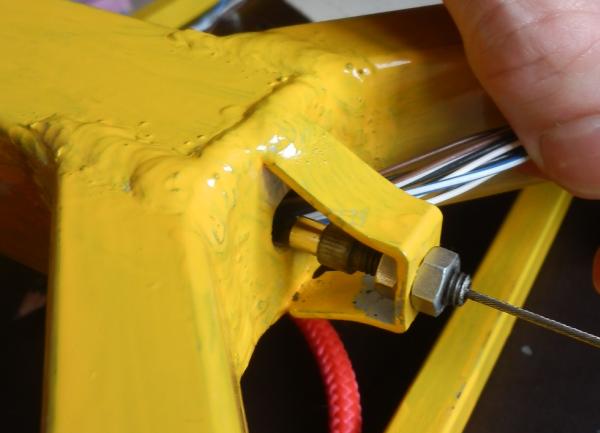
Insulation and waterproofing is done mostly by hot glue and some heat shrink tubes here and there. Everything should withstand any type of rain. Switches are exposed and that, after several rains, turned out to be a mistake: right indicator and blue lights suddenly died one day because water had gotten into the switches and they rusted:


Lesson learned: the only relatively waterproof parts are the lever's ball joint and the electric leads on the other side. The metal cover is a weak spot: there are gaps all around it, as well as between it and the threaded part. I'll have to make some housing for it all.
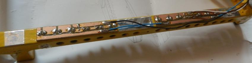
Cables are attached to the frame by wire, hot glue, electric tape, zip ties and strings, depending on what worked best in each place. The bundle of cables between mainboard and cargo module is hidden inside the midframe beam, all others are exposed. Pieces of heat shrink tubes and a thin black sharpie make the best cable markers.


Wires hot-glued to the smooth plywood cargo floor came loose after several months, so all the glued spots had to be secured by wood screws. Fortunately, several strategic spots were secured like that from the beginning, so nothing got torn off and lost. The second photo shows how to get a bundle of cables through a frame tube: first get just one wire through, then solder the others to its end, pull it back and cut off.
I think it went well. The powerful headlight provides enough light even for higher speeds than I can afford with the trike. Low beams are strong enough to be seen and to let me see the road when I creep up a hill, but not to blind anyone. I occassionally flipped a wrong switch at the beginning, but that was cured by practice.