


This setup is a sort of dead end of evolution. It excels in "to be seen", but is poor at "to see by" because the front white diodes have the largest threshold voltage and start to shine last of all. It's enough for a city, but not for slow night rides through uncharted wilderness. So as the classic said: don't go this way, my friends :-).
SON 28 dynohub laced in a 20" wheel provides almost 2 W more than usual at 20 km/h. Instead of drawing more current, I increased the voltage (upper limit 13.6 V) which allowed to install much more LEDs.
For the headlight, I originally planned a high-power LED with a parabolic reflector. The whole generated current would flow through it and then spread among the other smaller lights. I didn't have exact ratings for the big LED, so I measured the point where it starts to warm up too much: 3 V and 470 mA. This made the upper limit, rest of the circuit was calculated to fit the remaining power budget. My plan was foiled by two things: insufficient brightness of the LED (it needs several hundreds mA to light up properly, which means cca 25+ km/h) and insufficient reflectivity of the aluminium foil I used for the reflector. It looked good against a white wall, but black asphalt needs more. Second try: the one big LED was replaced by 25 twenty-milliamp ones connected in parallel. These need less current to shine. Together with some other white LEDs that were meant to supplement the big one it makes a total of 41 white diodes.
Ten red LEDs are packed in the old folder's taillight (one of them for standlight), another eight are hot-glued to rear mudguard stays and another four are up on the seatpost, housed in an old blinky shell. That means 22 reds in total. The cherry on the cake are 28 omnidirectional yellow LEDs placed at various places around the frame. Summed up: 91 diodes. I must be a megalomaniac.

(to make it simple: something||something means parallel connection of resistors)
Main switch S1 is placed unconventionally behind the rectifier. When in middle position, both poles are disconnected, the bridge is charged by full open-circuit voltage, but there is no current and therefore no power losses. One end position turns on the lights, the other turns on the charger. Quite an elegant solution that saves one control element, but finding the switched off position requires sensitive fingers - not always possible with thick gloves. But you can use a bigger switch if needed.
There's no point in connecting Zener diodes in parallel because they never have the exactly equal voltage thresholds and one of them would open first and suck all available current. If you need more wattage, connect them in series. Here I overbuilt the protection a bit, but it's not a bad thing, at least I don't have to worry about speed even with unloaded charger turned on.
I used a lot of old LEDs I had lying around in small numbers of each type, that's why the circuit is such a weird mix (actually there are five types of LED6, every single LED5 is different etc.). All of them needed to be measured and carefully paired, but it was worth the work, my parts bin finally cleared up. Yellow LED7 were found at sale, advertised as "ugly warm white" - I couldn't resist buying the whole box :-). As mentioned above, LED2 should originally be just one big; this parallel massacre is an emergency solution not recommendable for copying.
USB charger is a simple linear stabilizer again. This time I used LM2940 instead of 7805 because it is slightly more efficient and has an overload and reverse-polarity protection built in, so less external components are needed. Maximum input voltage is 30 V (when exceeded, the stabilizer turns off automatically), external Zener diodes limit it to 27.3 V. Fifty-volt smoothing capacitor C1 is rather bulky and takes up about one third of the circuit board. Lower-rated one might be enough, but electrolytic capacitors are generally not known for extreme reliability, so I played it safe.
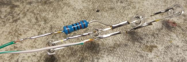
This time I used my own etched PCBs extensively and finally learnt to solder properly :-). Unlike the previous setups that had all the electronics in one place and two separate wires running to each light, I used a decentralized approach here: only two common "bus" wires run along the bike and every light has its resistor built in. It proved to be a good idea, next time I'll do it again.
Taillight PCB, modified seatpost blinky and one of the two serial/parallel quadruplets of yellow lights for the rear fork:


The blinky originally contained three LEDs, two AAA batteries and some electronics, but died due to moisture that got inside through the cracked shell. Now it got new internals, better sealing and a second chance.
The yellow diodes are soldered directly by their leads, hot glue takes care of insulation and mechanical protection. Taillight contains my usual serial/parallel set of nine red LEDs and the positive pole is routed through an external loop of cable, so theoretically it is compatible with my trailer lights. I don't plan to use it with this bike, but better to be prepared.
First version of the main motherboard:
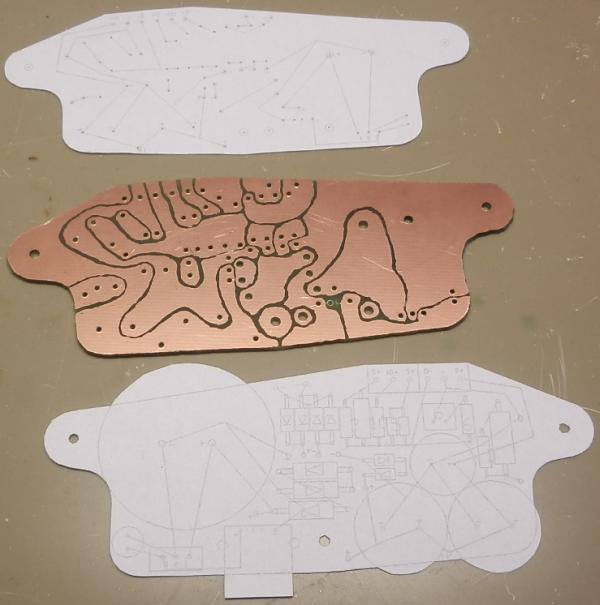

After an hour of pointless scrawling on a square paper, I moved to a computer where the drawn parts can be moved and edited. The result is a board filled up to the last square millimetre. The lever switch at the rear (above the USB) is S1, the second was originally meant to switch between the long-range LED and an equivalent resistor. This should have been a safety feature for case of the big LED failure - it was to be a bottleneck for the whole input power, so if something happened to it (loose contact etc.), everything would go black.
This is how it all fit together:


I used a waterproof industrial electric cabinet for the shell, with a plexiglass window glued in at the front. Most of the internal space was taken up by the parabolic reflector and capacitors. The separate housing for the small LEDs was necessary because they needed to be tiltable independently of the main light. By the time these pictures were taken, I didn't know I'm going to redo it all...
Reflector dish is made of cardboard, lined by kitchen aluminium foil:
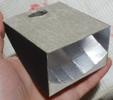


Shape of the dish is calculated so that it reflects the light more or less parallel in the vertical direction and with several degrees of divergence in the horizontal direction. By adjusting the light source position, the vertical distribution can be tuned so that most of the light is at the top edge of the beam and the road is more uniformly illuminated. The beam is cut off at the top, so if the light is tilted properly, id doesn't glare anyone. The theory is nice, the reality crashed on weak light source and insufficient reflectivity. If you'd like to try it yourself, here are templates for the dish.
Second version of the headlight:


One big diode was replaced by 25 smaller ones which were mounted to this board, together with all other white diodes (except one). Reflective plate was cut from some box, the holes are made with punch pliers.
Final look of the mainboard:


The circuit was simplified a little, two resistors and one switch were removed. Several jumpers were added to the bottom side to improve conductivity (common ground was inconveniently routed through the longest and thinnest copper path). Five terminals exit the box; I used a nine-pin port because it was at hand and because it can be bolted together securely. The high-current cables are connected to two pins at once.
It looks cool, although it's not as practical as I'd like. Notes to remember: most important lights (front and rear) should be connected in no more than six volt series. Higher threshold voltage should only be used for nonessential decorative lights where it doesn't matter if they shine at higher speeds only.